I got a feed back from Keksintösäätiö !
They see no reason to fund this plane.
2009-03-30
2009-03-27
Emergency exit and stepping in !

STEPPING IN:
- Lean first to the wing back towards prop/fan.
- Hop on the wing and hold up your left foot and place your right foot on the wheel.
- Place the left foot on the chair ( clean the shoes first ).
- Take a grip of the safety archs handle.
- Shift your weight to left and raise the right foot from the wheel.
- Slide into cockpit.
- Close the hatch/canopy rear section and lock it.
STEPPING OUT:
- Do everything mentioned above in opposite order:
EMERGENCY BALE OUT:
- Stop the engine.
- Unlock the canopy and push it out into slipstream ( it will come off ).
- Turn the plane inverted.
- Open the harness.
- You are out ( hopefully you parachute opens ).
Plane is equipped with a recovery parachute. Use it rather than loose the plane. Jump only in real emergency ( fire onboard or other good reason ).
The rear canopy is a oval half with 510x640 mm size ( you have to squeeze your shoulders slightly together to get in and out or twist your upper torso slightly ).
Still questions concerning this matter ?
2009-03-26
My wingloading chart
Incredible but true; quickie model 54 and max III have almost identical wing loadings.


Center of gravity and engine powershaft systems !
I talked to few experts today.
Jukka Tervamäki has a JT-11 design; http://www.icon.fi/~jtki/jt11virtual.html
It has all the same problems solved that my tiny pusher would also have to deal with.
I rely on the flexidyne coupling ( since I have a direct drive ). Meaning a stiff but yet rubber sunstance in the shaft between engine and the root of the shaft. Several available in the market.
I am more concerned now how I will get the model shaft done and working fluently.
-------------------
Kai Mellén said the handling of the CG in a small plane is very challenging ( he has designed two PIK-21 and PIK-26; 135 kg and 200 kg weighing small experimentals ). Making tails sufficient in size will help..long fuselage is also good. I already made lot of these changes after discussing with Jyrki Laukkanen.
-------------------
Jyrki Laukkanen and Jukka Tervamäki both said that the gyroscopic forces of the prop are not significant in a pusher layout like in MAX III. I have to rely on these expert comments on this matter.
2009-03-24
Am I still on the right track ?

Some questions have arisen if I am drifting into motorized glider department. Well see for your self..making this bigger will ensure the better flying caracteristics also for the shorter winged racer. I am still under the "competitors" when it comes to FPEA.
Prop has to be pretty high revving direct drive fan. This will possibly require more work than the whole project without it.
The 820 mm dia thin bladed fan has to go 5500-6000 rpm to be effective tips at pretty high mach number ( 0.75 at least ).
2009-03-23
"Sailplane" with a "closing prop" ?

Think about it. Fast motorised glider..able to seek new thermal at 175 mph !!! Could that prop be like in electric gliders..sorta folding in ?
Seriously I am not designing a glider, but this as a plane has some features of a good glider.
More wingarea !

I just had to go for this after stydying more. I want this to be safe and economical. This will be speedy enough.

I recently read that some real aviation companies make even 4.5% sized models of their designs to find out some details about them. That sized model of MAX III would be 28.45 cm in span.
2009-03-20
Could MAX III fly with a 3 hp model engine ?
I was asked this when I stated earlier that the best fuel consumption 0.69 liters / hour was obtained at 89 mph ?
Here is the proposed OS 120 AX; http://www.rcgroups.com/forums/showthread.php?t=478975
It produces 3.1 hp. Not bad.
I have earlier stated that landing gear alone produces more drag ( 2 x ) than the whole ac...and using flaps ( fully ) will also multiply the drag ( 4 x ).
This MAX III has half the hp:s as the Cri Cri ( 2 x 22 hp recommended ). Which weighs around 70-84 kg empty ( original Cri Cri had 2 x 9 hp engines and weighed 64 kilos).
In order to glide fast MAX has to have retracts and half the drag of an glider. The best open class gliders have 60 kg/m2 wingloading ( around the same as
MAX III with a heavy pilot and full load of fuel ).
To reach the record braking mileage of 450 MPG the MAX has to be very clean and relatively lite in order to cruise at 1.7 hp power ( almost half of what OS 120 AX produces ). Possibly it needs also plane to be very lite built ( even 70 kg or less ) and pilot not heavier than 75 kilos + prop optimized just for this speed.
So in theory 120 AX could do it but it would have to be towed into air...and no gusts or change of wind direction that would make pilot to use more power is not tolerated either. Also the torque of the engine to drive a reduction ( normally with 22 hp engine not needed ) gear might take 50% of the engine power out so perhaps we need a good thermal to fly MAX III with a OS 120 AX. : )
Thanks for the comment.
Here is how the very lite and underpowered models fare with MAX III:

2009-03-19
Learning from wing loading chart : )

I had to bring this project into direction I saw as the best way to go. As you can see MAX III has now decisively more wing and length and an old fashioned tail wheel. I have down graded the top speed and made this more like "a glider". Away from the "racer" class into the markets with potential customers.

Here is another good link to a study of pusher vs. tractor lay-out ac: http://aero-comlab.stanford.edu/Papers/AIAA-2000-4341-839.pdf
Wing loading PART II


Since there were some inaccuracies and lotsa interesting planes missing; Here is the table again.
Seems that some big R/C planes fly at relatively very low wingloading.
Below you can see how far from WW II planes the modern day fighter have "drifted". Far right is SU-27.

2009-03-14
WINGLOADING
I made a chart to see where MAX III is in comparison with other known aircrafts wingloadings.
http://www.aafo.com/hangartalk/attachment.php?attachmentid=12595&d=1237056434
For few WW II planes I drew a line from 1/12 scale models equivalent specs to real 1:1 scale one to give some perspective ( small models are a handful to fly...but very educative ).

2009-03-12
Latest mods

The plane is now exactly as long as the Bede-5B, that is 3880 mm. Tail wheel needs a little cover to avoids small rocks hitting the prop. Greatest range is 3500 nM at 90 mph ( mpg 490.5 ).
 Also the FPEA 0.245 sq ft record twin engine pusher has been under scrutiny to achieve lower drag and better controllability. This is also a taildagger design.
I am little bit curious; can you please comment which one of these would you choose if both were fluently tested to meet all required standards in aviation regulatory and were of the same price ( $ 45 000 or 40 000 € ) ?
2009-03-11
3000 hits in a month...reason to celebrate ?
Well I am pleased, but I'd like to get some pre-orders.


Has anyone even considered that this could be a cool ride, if properly managed and manufactured ?
NEW RUDDER AND TAIL GEAR ASSEMBLY
This will allow less damage on in beat field ended forced landings ( if necessary ). Will the free turning tail wheel be effective in taxiing ? I assume using throttle the rudder will be very effective ( because of the suction ) more than in a tractor lay-out design ( engine front ).

The tail wheel is a bit like this ( hopefully ) in Phantom; http://www.vimeo.com/3360538
Y-tail, V-tail or crusifix form ?
Here is a complete story of Bede-5b:
http://www.absoluteastronomy.com/topics/Bede_BD-5
Here is a pic of the very first Bede-5B with v-tail. No wonder it was unstable; the v -tail is way too small.
http://www.airport-data.com/aircraft/photo/040961.html

I have discussed this pusher V vs. Y tail issue several times with aeroengineer Eric Ahlstrom and the Y tail has been recognized as the valid form for this kinda pushers. His DART design had such and seen here; http://www.renaissance-research.com/projects/
I wonder why Bede did not put the rudder in the end of the fuselage and leave the V work as a rudder stabiliser and working elevator.
The safety record of BEDE-5B was terrible:
Insert from the link above,
Over the next few years the aircraft garnered what at first glance appears to be a terrible safety record. The earliest kits shipped with the short "A" wings (optionally), and all four examples completed with these wings crashed on their first flight, with three fatalities, largely a side effect of a 100 mph (160 km/h) landing speed combined with the tiny wheelbase. Nevertheless the current record holder of the FAI C-1a/0 (300 kg or less takeoff weight) class speed record over a 3k m course at restricted altitude is a BD-5A (listed as BD-5B but used -5A wings for the record attempt) with a Rotax 618UL 74 hp two-stroke, three-cylinder water-cooled engine..Most of the crashes of -5B models can be traced back to pilots who were not prepared to fly the aircraft. It is not uncommon for kit or plans-built aircraft builders to spend years on their projects and neglect their currency requirements to maintain their pilot skills. Many accidents took place because builders were in too much of a hurry to fly an aircraft that was not truly airworthy. Several crashes in the -5B models were found to have taken place due to engine failure on takeoff, both due to the mix of "oddball" engines as well as endemic cooling problems.The reason this is such an issue with the BD-5 is two-fold – the high line of thrust means an engine failure immediately results in an unexpected (for most pilots) nose-up attitude change. Pilots who fail to fly the aircraft first and then attempt to restart the engine inevitably stall, with the associated consequences. This was aggravated by the fact the original wing had a very sharp stall with little warning and a nasty tendency to "snap roll.". To make matters worse, a documented manufacturing error in some wing skins delivered to kit builders exacerbated the problem. A rather small center of gravity range also added to the problems of properly trimming the aircraft.
I think I have solved all problems stated above.
1. I don't have a small wing option ( like VmaxProbe..very little wing and no wash out )
2. Landing speed is normal ( 65-80 km/h ).
3. High line of thrust is now like centerline ( with wing that is shoulder level positioned ).
4. Wing foil will be studied to be ideal for a small plane.
5. Bigger tailfeather area will ease the small ( narrow ) CofG problem ( also the movable seat will help ).
6. Cooling problem is handled with a totally new system with ram-air effect.
Molton Taylors first big success the Taylor Aerocar inflight. http://www.youtube.com/watch?v=NQ_D22Me_4A http://www.youtube.com/watch?v=GUgJOnhXorc&feature=related
It has got the Y-tail as well.
http://www.absoluteastronomy.com/topics/Bede_BD-5
Here is a pic of the very first Bede-5B with v-tail. No wonder it was unstable; the v -tail is way too small.
http://www.airport-data.com/aircraft/photo/040961.html
I have discussed this pusher V vs. Y tail issue several times with aeroengineer Eric Ahlstrom and the Y tail has been recognized as the valid form for this kinda pushers. His DART design had such and seen here; http://www.renaissance-research.com/projects/
I wonder why Bede did not put the rudder in the end of the fuselage and leave the V work as a rudder stabiliser and working elevator.
The safety record of BEDE-5B was terrible:
Insert from the link above,
Over the next few years the aircraft garnered what at first glance appears to be a terrible safety record. The earliest kits shipped with the short "A" wings (optionally), and all four examples completed with these wings crashed on their first flight, with three fatalities, largely a side effect of a 100 mph (160 km/h) landing speed combined with the tiny wheelbase. Nevertheless the current record holder of the FAI C-1a/0 (300 kg or less takeoff weight) class speed record over a 3k m course at restricted altitude is a BD-5A (listed as BD-5B but used -5A wings for the record attempt) with a Rotax 618UL 74 hp two-stroke, three-cylinder water-cooled engine..Most of the crashes of -5B models can be traced back to pilots who were not prepared to fly the aircraft. It is not uncommon for kit or plans-built aircraft builders to spend years on their projects and neglect their currency requirements to maintain their pilot skills. Many accidents took place because builders were in too much of a hurry to fly an aircraft that was not truly airworthy. Several crashes in the -5B models were found to have taken place due to engine failure on takeoff, both due to the mix of "oddball" engines as well as endemic cooling problems.The reason this is such an issue with the BD-5 is two-fold – the high line of thrust means an engine failure immediately results in an unexpected (for most pilots) nose-up attitude change. Pilots who fail to fly the aircraft first and then attempt to restart the engine inevitably stall, with the associated consequences. This was aggravated by the fact the original wing had a very sharp stall with little warning and a nasty tendency to "snap roll.". To make matters worse, a documented manufacturing error in some wing skins delivered to kit builders exacerbated the problem. A rather small center of gravity range also added to the problems of properly trimming the aircraft.
I think I have solved all problems stated above.
1. I don't have a small wing option ( like VmaxProbe..very little wing and no wash out )
2. Landing speed is normal ( 65-80 km/h ).
3. High line of thrust is now like centerline ( with wing that is shoulder level positioned ).
4. Wing foil will be studied to be ideal for a small plane.
5. Bigger tailfeather area will ease the small ( narrow ) CofG problem ( also the movable seat will help ).
6. Cooling problem is handled with a totally new system with ram-air effect.
Molton Taylors first big success the Taylor Aerocar inflight. http://www.youtube.com/watch?v=NQ_D22Me_4A http://www.youtube.com/watch?v=GUgJOnhXorc&feature=related
It has got the Y-tail as well.
2009-03-10
MacRobertson Air Race 1934
While I am waiting for the funding for MAX III I'll make a brief jump into history and see how MAX would have succeeded in the famous MacRobertson AIR RACE of 1934.
http://en.wikipedia.org/wiki/MacRobertson_Air_Race
Dh 88 Comet was well represented in the race;
http://en.wikipedia.org/wiki/De_Havilland_DH.88
Trip was 18 182 km or 11 300 miles with 5 compulsory stops at Baghdad, Allahabad, Singapore, Darwin and Charleville, Queensland. Start was at Mildenhall England and goal was to reach Melbourne Australia as soon as possible.
Race was very heavy since of 20 planes only 9 reached the in due time. 11 were disqualified or destroyed.
First leg from Mildenhall to Baghdad is 2530 miles and Dh Comet Black Magic reached there in 12 h 40 minutes; http://www.flightglobal.com/pdfarchive/view/1937/1937%20-%201918.html
For Max III with 22 hp engine it would have taken 13 hr and 45 minutes and burned 36 liters ( 9.5 gallons ) of fuel ( lets assume Max II had 50 liter tanks for the race ). Black Magic had 257 gallon fuel tanks ( for a London Lisbon race it needed to take 170 gallons onboard ).
Next leg from Baghdad to Allahabad is 2300 miles. http://www.abc.net.au/local/stories/2007/10/20/2064985.htm
This is where mr and mrs Mollisons trip with Black Magic ended and another DH Comet Grosvenor House took the lead.
This leg would have taken 12 hr and 25 min for MAX III to complete with 8.6 gallons of fuel ( 32.9 liters ).
From Allahabad to Singapore the distance is 221o miles ( 3555 km ). 12 hours flying for MAX III with 8.3 gallons fuel burned.
Singapore to Darwin is only 2084 miles ( 3353 km ). After 11 hr 15 min flight MAX III would have arrived in Darwin ( fuel burned 7.8 gallons ).
Next leg being only 1389 miles Darwin to Charleville crew chief of MAX III decides to use nitrous enhanced fuel increasing speed to 220 mph and fuel burn to maximum 50 liters for this leg. This pays off; Max arrives after 6 hr 18 min flight.
After the change of engine ( to a 50 hp ) the last trip is taken from Charleville to Melbourne ( 850 miles ) at incredible speed of 240 mph ( slight tailwind ) using all 50 liters again. This takes only 2 hr 32 minutes for MAX III to travel.
After 58 hours 5 minutes of flying and 4 stops of 2 hours ( cleaning and eating + refuelling + engine change + 1 hour nap ) and one good sleep in a hotel in Singapore ( 4 hours and all fuelling included ).
Max III would have arrived in 70 hr and 5 minutes in Melbourne beating Grosvenor House by just 55 minutes.
2009-03-09
Frontal area vs. flat plate equivalent area !
 I had to do some corrections; due to the enlarged tail feathers and despite being lighter and smaller in size MAX III will never reach the VmaxProbes estimated gear retracted FPE area of 0.31 sq ft ( I already tought we gonna go under with flying colours, but no..we come near though ).
Albeit frontal area has practically nothing to do with flat plate area the cross section area is many times used indicating the achievable drag of the fuse. In MAX III it is 0.31 m2 ( 3.38 sq ft ). Generally in small planes of low wing lay out it can be 5.0 sq ft ( o.46 m2 ) like in Ar-5 and Bede-5b.

To know more about small ACs drag; http://www.aerodrag.com/dragbook/dragbookfinal0627.doc
2009-03-08
What a drag ! : )
I read that originally VmaxProbe was intented to fly with 0.31 sq ft drag . Later drag rose to 0.45 sq ft still the lowest drag ever recorded in an propelled aeroplane ( in fact in any manned aircraft ) when plane had no retracts.
I wonder how the 0.31 was obtained ?
Ok I assume short laminar wing with very little wing area and NACA studied fuselage.
I did my calculations based on AR-5 calculation of B. Carmichael and I got 0.339 for my AC and if lucky in foil selection then 0.318 ( due to overall smaller size [ weight also ] of the plane and use of retracts ). I assume pilot would have to lie down in prone position to go under 0.300 in drag ?
In theory it could be..here is my prone position flown lifting body twin pusher fan ( drag 0.277 sq ft when some interference added):
This drag of going under .280 is interesting if you check nomograph in my earlier topic ( calculations in Bruce Carmichael style ) you see that I could get 170 mph speed with just 5 hp and 275 mph with 50 hp ( possibly 300 mph when enhanced ). That is why I say here again as I said before...never to build this small lifting body plane...it has very difficult bale out changes ! This is just an example of what can be done with lifting body ( in bigger scale ). This could be propelled with two inline 2 cylinder 2-stroke 20 hp APT engines. Plane woud have ram-air cooling and retracts ( taildagger ). This would require extensive windtunnel testing to find the proper size and form for the fuse and wing.
The extremely low drag coefficient is reached with a laminar flow: http://www.aviation-history.com/theory/lam-flow.htm ( Bruce Carmichael used coefficient 0.0029 for the fuse of AR-5 )
2009-03-07
Cost of flying to Tenerife from Helsinki with Max III
I keep imagining, but basing my estimates on calculated specs.
Distance from Helsinki ( Capitol of Finland ) to Tenerife in Spanish Canary Islands ( on the Antlantic Ocean ) is 2901 miles. http://www.distance-calculator.co.uk/distance-from-helsinki-to-santa_cruz_de_tenerife.htm
At 90 mph the mileage is 490.5. That makes total use of gas to be 5.91 gallons ( 5.91 x 3.8 = 22.47 liters ). Flying time would be little less than it took Charles Lindbergh for crossing the Atlantic Ocean namely 33.27 hrs.
In South American oil producer nation Venezuela the gas costs $ 1 / 90 liters ( I saw a document recently on TV ). So the trip to the Canary Islands would cost .25 cents ( less than 20 european cents ) in Venezuelan cost of gas. In fact from Caracas ( Venezuela ) the trip to Tenrife ( Spain ) is only 2643 miles ( less than 20 cents ). http://www.theairdb.com/airport/CCS.html
In finnish gas price the trip to Tenerife from Helsinki is 22.47 x 1.25 € = 28.09 €:s. Not very expensive.
Traveling at cruise speed of 165 mph the use of gas to Tenerife would take 44.14 liters ( 10.9 gallons ) and time spent would be 17.58 hours. Trying to travel any faster would require much more fuel and/or a bigger engine. Theoretically 200 hp ( 29 kg ) AVEC engine could propel MAX 3 to Tenerife in 6.5 hours ( flying hrs ). With 50 HP Limbach the trip would be 12.0 hrs flying hours but plane would have to make 2 stops to refuel ( if double size tanks; 110 liters ).
PS: I have "slight" mistake in the header text for the range...it should be 3500 nM ( nautical mile is 1.8 km ) with 30 liter tank.
2009-03-05
What a difference a PROP makes !
http://www.eaa.org/experimenter/articles/2009-02_elippse.asp
90 % efficiency obtained by Ellipse prop !
-----------
It is funny but for ten years no as I have been designing aeroplanes I have always drawn it close to that kinda prop which has a wide root almost parallel to fuse and thinner at tip by instinct. I get good vibes about it...strong and efficient at the same time..no bad vibes during the flight.
Unfortunately i think I have to design my own prop for the Max III, since no one makes 820-880 mm dia 4 bladers...nor 2 or 3 blabers for pushers. How hard can it be ?
2009-03-04
Suction of air by a fan
I made very simple empiric test.
I had an air circulator dia 40 cm and a tachometer ( for R/C models ) and toilet paper.
I had the fan running at low speed about 1100-1200 rpm ( indicated ) and at full power at 1900-2100 rpm.
At 40 cm distance the suction was such that the 3 piece toilet paper strip was sucked into the prop at full 2000 rpm. From 50 cm the paper was leaning 10 cm to the prop direction.
Also at 1100 rpm at 40 cm the paper leaned 20-25 cm into prop...and from 50 cm only few cm:s.
---------
Aeroplane fans like in MAX III will operate at 820 diameter faster than 3500 rpm ( in fact even 6200 rpm is not supersonic at that size )....so I have a feeling that there is no way a tailfeather could stall as the prop turns causing thrust greater than the prop:s drag as long as the prop is not further than 30 cm ( rather like 200-250 mm to be sure ) from the elevator / rudder combo. Slight disadvantage of turbulence by the 10% thick feathers can only make minor difference in speed or efficiency whether it is 250 mm or 400 mm away. OTOH it will make big difference as a distance increase from aerodynamical center which has to be compensated with tailfeather and in torque related situations with ailerons ( see the german designs had tailfeathers really close to the prop ).
I would very much like to see some windtunnel data on this prop suction caused powersteering feature. Not to be neglected in any case. I have a haunch a strong braking with the prop would cause less adequate steering caracteristics with pitch and yaw.
2009-03-03
Max after testpilots comments
I have been in touch with retired FAF testpilot ( who is also an aviation engineer by education ) mr. Jyrki Laukkanen ( like I mentioned earlier ). His expertise and my enthusiasm has been very fruitfull. He knows aeroplanes and their flying caracteristics possibly better than anyone in this country. Albeit his reluctance to see much positive aspects in a pusher in the first place I see his generous help to make this plane better has been obvious.

1. First he insisted to make the plane longer ( I added first 220 mm then 150 mm more ).
2. Yesterday he threw ( in e-mail ) me a minimum rudder area to be added to make this kite directionally stable ( it was so much rudder that I won't even show it to you ), but that made me think thoroughly the rudder aspect.
First the rudder ( directionally affecting stab area ) is now bigger than in Bede-5B ( fractionally ) and the rudder itself is fractionally bigger than in VmaxProbe.
To make the negative V effect smaller I drew the rudder less high than before, but added more depth and thickness to it to make it effective. I also increased the V-form and size of the elevator/vertical stabiliser considerably. I also made solid stabilizer since i figured the rudder was going to be too heavy ( and Jyrki Laukkanen saw no reason to have it ). All this has been adding the wetted area, but all this tuning has kept the total area very respectable in goal to achieve a flight with a 22 hp engine. I might also add that this AC:s aerodynamics will also be good with a 40-50 hp engine ( this will naturally inrease wingloading and speeds + fuel consumption = less flying time unless bigger fuel tanks ).
The enclosed comparison has some reference lines of the wing and rudder positions drawn above the profiles that you get a better idea how these planes are in relationship to each others. This doesn't make much sense because it is like comparing sweet potatoe, orange and carrot, but they all are high performance pushers ( axial thrust fans ).
Bede-5B wingarea is around 4.4 m2
VmaxProbe was 2.45 m2
Max III is 2.9 m2 ( fowler flaps extended 3.2 m2 )
2009-03-02
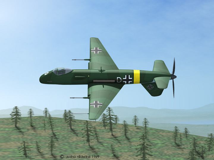
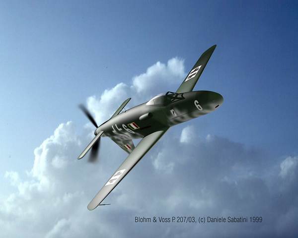
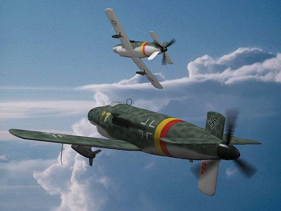
Luft46 axial thrust fans...
Let me show how aviation engineers saw this directional stability problem solved in Germany back in the forties.
B & V P.192.01 http://www.luft46.com/bv/bvp193.html
http://www.luft46.com/jhart/jh193-1.jpg
B & V 207-3: http://www.luft46.com/bv/bv207-3.html
http://www.luft46.com/dsart/ds207-3.jpg
B & V 207-2: http://www.luft46.com/bv/bv207-2.html
http://www.luft46.com/tpart/tp207-5.jpg
Me 334: http://www.luft46.com/mess/me334.html
P 192.01 has striking similarities with both A-10 and A-9 ground attack plane programs.
New tail feathers

Since I don't want to argue about advices I agreed to increase the elevator area by 5%( and its rudder 15%) and altogether the directional stability affecting rudder area by 20 %. It is visible to the eye and believe me..it is there..the angle of elevator V-form has increased...a lot.
It is a lot like Sierra Sue rudder now.

Not far from Lear Fan 2100 projected rudder lay-out, which has very small under side positioned rudder.

How much rudder do I have ?

Here is a funny pic..all rudder components from elevator has been added to the underside rudder and turned 180 degrees. Also the fuse is very slim which increases the stability..and the gyro forces of the prop ( unless it doesn't turn ).
I wonder does the suction from the prop cause more effectivenes to tail feathers..any study of that available ?
0.33 m2 is the total rudder area...fuse section is 0.31 m2 at the thickest point. This is slightly 2% more rudder area than in VmaxProbe and 10% less than in Bede-5B ( which has 30% more wingarea ).
Here is plane by Kurt Tank that has quite small ( in profile ) but thick rudder ( large in cubature ) : http://en.wikipedia.org/wiki/Fw_190
Slightly this is what I am after...a rudder that will reattach flow quickly if flow is lost in a spiral etc. Also the whole rudder with stab turns in MAX III.
Here is too little rudder: http://www.if1airracing.com/IF1_Planes.php?aircraftID=263 for 66 sq ft wing ( Max 3 has only ½ of that wingarea and 1/3 to 1/4 th of the power and weight ). Note they added 1 sq ft of vertical to plane in the pic.
Little bit more length

Here is the last update of the day...150 mm more length..this way I don't mave to increase the elevator area and coefficient in fuse will be better.
I might stop talking about the laminar flow in radiator and accept 4 % drag for cooling. I have continous flow, but laminar flow doesn't cool much so it has to be made sligthly turbulent. I think my cooling intake like in Pond Racer and Mini-Imp is outstandingly positioned to reduce interference drag in the wing-fuse juncture. The air will become more kinetic by heating and thus it has the ram-air effect..but less laminar aspect. I might have mixed these terms together.
Incredible mileage of 490 at 90 mph speed
I calculated at 90 mph speed that MAX needs 1.65 hp ( just little more than in a lite scooter/moped ). That means 0.697 l/hr and thus 490 miles with a gallon ( 3.8 liters ).
Limbach L275E engine SFC was used to calculate this.
APT engine at 65% gives mileage of 260 at 165 mph ( no SFC chart available ). Limbach at 65% "only" gives mileage of 85.
This is amazing in an AC, but "Pisaralla pisimmälle* " fuel economy competitions have been able to go 4050 km with a litre of fuel ( mileage of 10 000 ) driving a wheeled vehicle by a lite person. My estimates for AC are based on 110 kg of load.
* furthest with a drop ( translation from finnish ).
What does this economy mean in practise? It means that if you take off from Helsinki and head for Cape Town in southern Africa ( 6480 miles or 10430 km ) you will arrive there 72 hours later and you have burned 50 liters of fuel ( 13 gallons ). Weather permitting and winds favourable allowing to cruise average of 90 mph. APT at 65% would get you there in just 39 hours.
It could also make the trip from Helsinki to Melboune Australia possible with everyman's purse at 105 hours of flight at 93 liters of fuel ( 15 180 km/ 9430 miles ). Using APT at 65% power youd arrive in Melbourne 57 hours later. Flying over 20 hours is not very eazy task so 2 refuellings are recommended .
All this means MAX III is not yet ready to travel very far fast enough.
Let's see the trip to New York from London 3470 miles ( 5585 km ). It would take 13.4 gallons ( 51 liters ) and 21 hours at 65% using APT engine. That is doable I recon.
For Charles Lindberg it took 33,5 hours to fly the same distance from Nova Scotia to Paris in 1927. http://www.eyewitnesstohistory.com/lindbergh.htm
Just to mention how dramatically fuel efficiency drops is that MAX would use 27 liters to go 250 mph with a 50 hp engine. With 40 minutes reserve it could possibly go 900 miles with 100 liters tank. You could get to Biarritz from London just under two (2) hours using the speedier version of MAX III ( using just under 50 liters of fuel ).
Here is the SFC of Limbach L550E: http://www.limflug.de/files/pdf/DS-L550E.pdf
2009-03-01
Drag calculations in Bruce Carmichael style...
I made a preliminary calculations that my Max 3 has a drag of:
WING 0.134 sq ft
IND.D 0.008 sq ft
FUSE 0.125 sq ft ( + rudder...same wetted area coefficient 0.0027 )
W+B.I 0.012 sq ft
ELEV 0.031 sq ft
--------------------
ALL 0.310 sq ft
Total drag coefficient based 0n wing area in 0.0120
Total wetted area dragcoefficient is 0.0015 which can be considered phenomenal !
Previously only VmaxProbe had close to similar figures and P-51D Mustang 0.0040 ( AR-5 0.0034 ).
There is no drag by cooling ( like in P-51D ) and the gear ( since it is retractable ).
That is less than half of the drag of a 3 feet longer and 1.9 sq ft more fuse cross section possessing AR-5 record setter.
http://www.ar-5.com/condrag94.html
NOTION; The fuse and rudder being non lift producing may have a coeffient .0025 which would yield 0.116 sq ft drag and making total drag into 0.301 sq ft. That would be 34 % of AR-5 drag and enabling to reach AR-5 speed with only 26,65 hp engine ( 213 mph ). This sounds plausible since Vmax Probe was calculated at 85% prop efficiency to go 240 mph with 50 hp. We have nowadays props that can go up t0 90% efficiency. It is also possible that my wing can be made with a lot less drag with some new foil ( instead the NACA I had as a basis ). Big wing will be serving the landing and take off behaviour...so I won't reduce the size to keep the landing more loading at 65 kg/m2. Wing being 0.120 sq ft drag the whole equation can be 0.287 sq ft ( 33 % of the AR-5 ). You see what I am getting here..checking if I could go 218+ mph with just 22 hp engine enhanced with nitrous oxide ( in theory it seems possible since with 90% efficient prop Max needs only 20 hp now with a super wing and fuse..nitrous will enhance the power output easily by 8-10 prosent ).
Who is going to say pushers have no advantage when it comes to drag issues ?
Also packing everything in a really small and yet compact size pays off.
You don't have to trust my estimate for the speed...just check the hp with 90% ( or even the 85% ) prop efficiency and use my calculated 0,31 sq ft for drag:
Minimalist AC instruments
http://www.youtube.com/watch?v=UIOYE6FQaDk&feature=related
There is a MC 15 Cri Cri by Colomban. I see 4 meters and a compus and "kugel".
I wonder what does those imstruments approximately cost ?
Altimeters from $ 24 to $ 225; http://motors.shop.ebay.com/items/altimeter_W0QQ?_rdc=1
There is a MC 15 Cri Cri by Colomban. I see 4 meters and a compus and "kugel".
I wonder what does those imstruments approximately cost ?
Altimeters from $ 24 to $ 225; http://motors.shop.ebay.com/items/altimeter_W0QQ?_rdc=1
Max III on floats
Here:
The main floats have to operate so that water splashes will be more on the outboard direction. Tailfloat prevents water from hitting the prop.
Subscribe to:
Posts (Atom)